That's sound like more than it is, so let's look at what's involved:
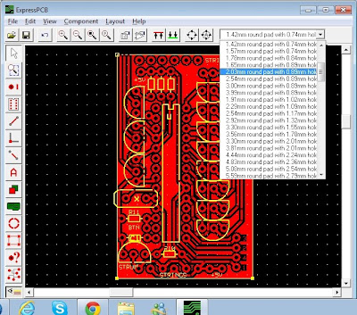
Firstly, create your schematic and PCB layout in ExpressPCB. When placing pads, use pads with 2.03mm size and 0.89mm hole:
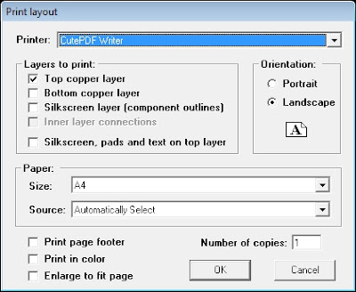
Print the top copper layer to a PDF file using CutePDF
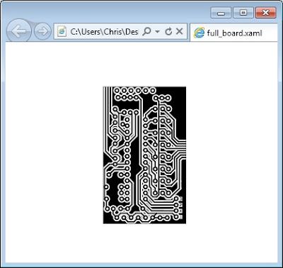
Open the PDF file in Inkscape and save as .xaml
The .xaml file should open with later versions of Internet Explorer (amongst others) so you can check the conversion worked properly. Open the file in Notepad to see all the complex XML shape descriptions.
Now start up the VB app and provide it with the path to the .xaml file
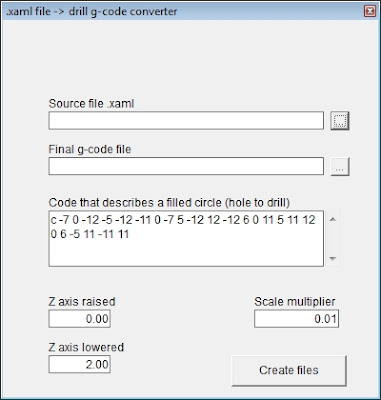
There are a few parameters to mess about with here. The main one is the code that describes a circle. If you've used 2.03mm pads with 0.89mm holes, this should be c -7 0 -12 -5 -12 -11 0 -7 5 -12 12 -12 6 0 11 5 11 12 0 6 -5 11 -11 11. You should see this set of commands repeated throughout the .xaml file, each time preceeded by [mX Y] type commands. If you've used different pad sizes, look for something similar - a repeating set of draw commands at different positions, with a fill colour of #FFFFFFFF (the [mX Y] commands are movement commands, the fill colour is white: basically we're looking for the repeating white circles that make up the centre of all the pads).
At the minute, we're not sure what units the .xaml file uses compared to our CNC machine - it will take a bit of messing about to get this right, so there's a scale multiplier parameter. As the app finds all the drill holes, it applies this multiplier, to convert from screen units/co-ordinates to whatever units the CNC machine uses. The final parameters to set at the Z-axis movement axis. The app will create some G-Code which can be loaded straight into the CNC controller software (we use Mach3 but may change once the demo version runs out!). Depending on whether the machine is set up to use inches, mm, or some other unit, this value may need to be changed - it defines the start (retracted) and end (plunged) position of the Dremel for drilling.
Pressing the "create files" button generates two files - one an amended .xaml file, so you can see a preview of the drill pattern generated. Load this into Internet Explorer (or some other software that lets you view .xaml) so see the final output.
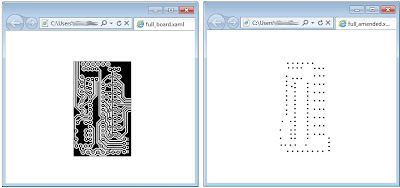 The original and amended .xaml files showing drill hole positioning
The VB app also creates a CNC-ready G-Code file with the points plotted, complete with "move-to" commands and "extend/retract drill head" commands.
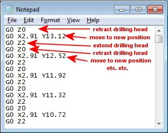
Load the G-Code into the CNC controlling software and let it go!
Download the VB app here

No comments:
Post a Comment